with Dot-Matrix LCD Display for
Microchip PIC16F84
Concept
How it works
Specifications
Features
Limitations
Project Resources
Available PIC Assembler
Code
Schematic, Data Sheets,
Pinout
User-specific
Customization
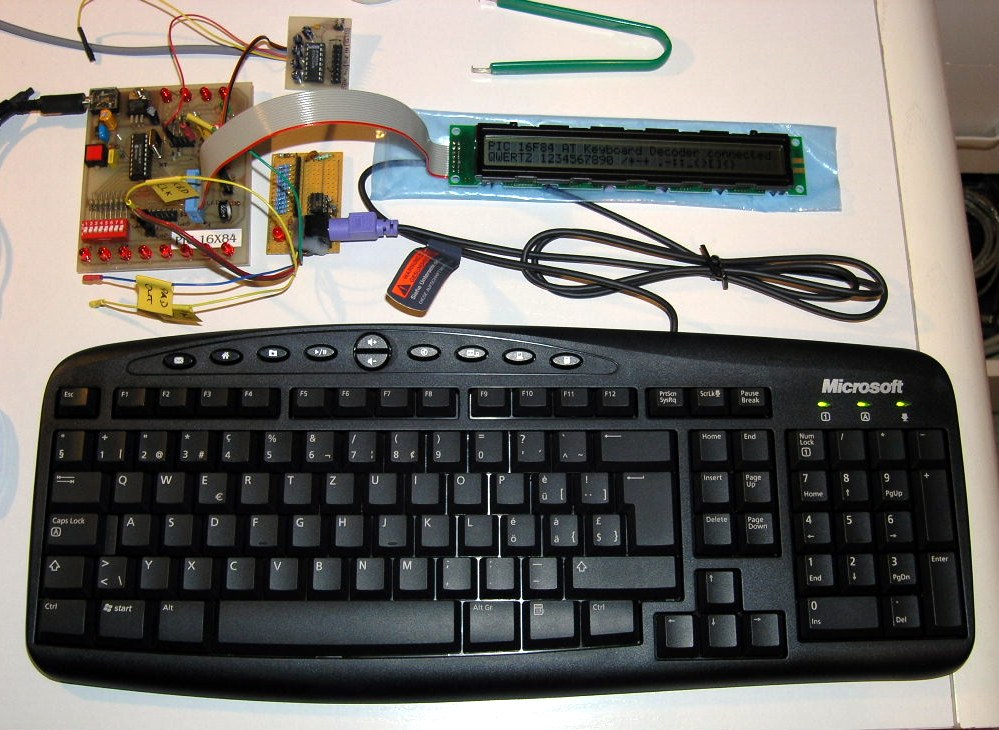
This implementation contains the complete fetch and decoding of AT keyboard scan patterns as well as RS232 transmission of ASCII characters to the RS232 target device. It also features an interface to a dot matrix LCD display to visualize the characters typed on the locally attached keyboard.
|
A recent picture of my workplace connecting a Microsoft PS/2 AT keyboard to the PIC16F84. |
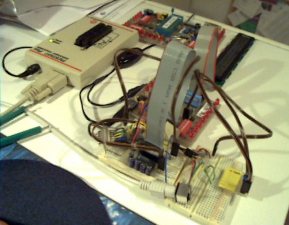
An elderly picture of my workplace, at which the initial development took place. |
Any key stroke on the local keyboard will send the
corresponding scan patterns from the keyboard to the PIC
microcontroller. Afterwards, the microcontroller converts the
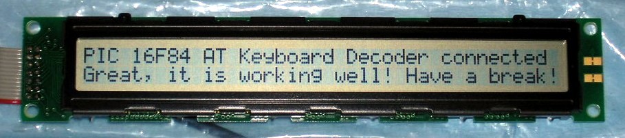
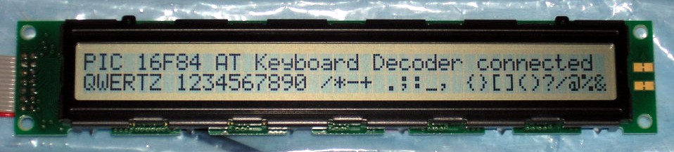
keyboard scan patterns to ASCII characters, shows them on the LCD
display and transmits them to the RS232 target device.
The keyboard scan code capture is done by an interrupt service
routine. The event, which triggers the interrupt is a falling
edge on the keyboard clock line (PORTB,0). Keyboard scan pattern
acquisition takes place at the keyboard data line (PORTA,4).
After 11 clocks (i.e. 11 external interrupts on RB0/INT), the
interrupt service routine has completely captured an 8 bit
element of the entire scan pattern and sets a ready flag. The
decoding of this 8 bit element is then carried out during normal
operation mode, activated by a valid ready flag whilst keeping
the keyboard stalled (keyboard clock line low).
The fact, that the scan pattern acquisition is carried out using an interrupt service routine and the decoding thereof is done during normal operation mode allows for performing other tasks concurrently: That's why I call the acquisition routine preemptive. It does not block the processor while acquiring data.
Only RS232 transmission is supported by this program, since PORTB,0 interrupt is already used by the keyboard clock line. There exists no possibility to implement also RS232 reception using my modules m_rsxxx.asm, because they require PORTB,0 as well and are laid out as non-preemptive data acquisition routines (see also 'Limitations').
For dedicated code adaptations, please refer to the section 'User-specific Customization' below.
If you don't know the theory of AT keyboards, have a look at
my short
introduction or at Craig Peacocks tutorial about Interfacing the PC's Keyboard.
| Processor: | Microchip PIC16F84 |
| Clock Frequency: | 4 MHz crystal |
| Throughput: | 1 MIPS |
| RS232 Baud Rate: | 9600 baud, 8 bit, no parity, 1 stopbit |
| Code Size of entire Program: | 984 instruction words |
| Keyboard Routine Features: | Capability of bi-directional communication between microcontroller and keyboard |
| Acquisition Methodology: | Preemptive, interrupt-based keyboard scan pattern acquisition, decoding to ASCII characters during normal operation mode activated by ready flag |
| Required Hardware: | AT keyboard, PS/2 connector, MAX232, HD44780 compatible dot matrix LCD (2x16, 2x20 or 2x40 characters) |
| Required Software: | RS232 terminal software (or Excel 97 RS232 Debug Interface) |
Basically the same limitations as for AT Keyboard Interface V1.xx.
| Main File | Main Keyboard Decode Lookup Table | SHIFT Keyboard Decode Lookup Table | HEX Files |
|
Latest version: Slim version without ALT-DEC & CTRL-HEX feature: |
English 'codepage' (QWERTY) View: eng_main.html Download: eng_main.asm |
English 'codepage' (QWERTY) View: eng_shif.html Download: eng_shif.asm |
QWERTY 'codepage': QWERTZ 'codepage': |
| Modified Swiss German 'codepage'
(QWERTZ) View: ger_main.html Download: ger_main.asm |
Modified Swiss German 'codepage'
(QWERTZ) View: ger_shif.html Download: ger_shif.asm |
||
| The above programs need
additional include files (modules) to
get successfully assembled: m_bank.asm, m_wait.asm,
m_rs096.asm, m_lcd_bf.asm Important: Due to bi-directional communication between controller and keyboard as well as between controller and LCD display, the above programs only work if both components are connected and are working properly! |
|||
| For those, who are not familiar with interfacing a PIC to the RS232 using a MAX232: RS232-Interface.pdf (9.7 kB) | |||
AT Keyboard Specification (PDF, 189 kB)
The schematic of the AT keyboard interface using the PIC 16F84: Keyboard_V2xx.pdf.
You don't know how a dot matrix LCD is working? Have a look at my data sheets page.
Download ASCII Character Map: ASCII-Map.pdf
You can get the description of the various keyboard connectors
<here>.
For a high level view, please refer to the section 'How it works' above.
Basically the same customization as for AT Keyboard Interface
V1.xx applies to this implementation.
If you apply changes to the existing code, you may need to change the ORG directives in order to realign the assembler code properly.
Last updated: 2006/04/17