PIC FAQ Section
Frequently asked questions for
Microchip PIC 8 bit microcontroller programming
Table of Contents [Toc]
How I started microcontroller
programming
Why I use PIC microcontrollers
How to start with PIC
microcontrollers?
PIC16F84
PIC16F77
PIC16F877
Which development environment do I
use?
First steps in PIC programming
Valuable Quick
References
Common
programming questions
How to assemble PIC code in
MPLAB
Advanced steps in PIC
programming
General
Paging - large
code considerations
Using the MPLAB IDE
simulation infrastructure (MPSIM)
High-level languages
C
compiler
List of free C
compilers
Commercial C
compilers
Debugging hints
General
Compile messages &
sanity checks
Prevent
page crossings of tables
RS232 communication
issues
LCD communication
issues
In case of errors
Compile
errors
Page crossings
PIC history
Call it RISC...
Scientific
curiosity
From I/O handling to
RISC controller
How I started
microcontroller programming [Toc] [Top]
I first entered the microcontroller world with a proprietary,
mask-programmed controller kit bought from Conrad Electronics, a
german electronics distributor. It was a Conrad C-Control
Basic kit, a 68HC05B based controller board with RS232 link
and an external serial EEPROM as program memory. The user
develops its application in a kind of BASIC programming language,
which is afterwards translated by the development software into
byte-tokens. The byte tokens are then loaded into the serial
EEPROM. During execution, the controller reads these byte-tokens
from the external EEPROM and interprets them using the internal,
pre-programmed routines. For first contact with microcontrollers,
it was a good approach, although there were some unsatisfying
facts:
- proprietary solution using mask-programmed routines in the
controller
- rather slow execution and low performance
- very limited data RAM
- no tight control of hardware resources and its
capabilities
- an expensive solution if used in pervasive computing (a
single and simple mask-programmed controller unit without board
costs about 25 US-$)
These reasons have led me to change to another controller
solution. Finally, I decided to change to the Microchip PIC
controllers.
Why I use PIC
microcontrollers [Toc] [Top]
The Microchip PIC microcontrollers are a convenient and
cost-effective solution for a lot of home-made applications,
because:
- PIC microcontrollers are widely available (Farnell, Conrad,
Disterelec,...)
- PIC controllers are cheap and do not require a lot of
prerequisites before running in an application (i.e. additional
HW blocks such as external EPROM for program memory, external
A/D converter,...)
- the PIC development environment is freely available and
up-to-date
- there is a broad range of different PIC microcontrollers,
very likely to fit into your target application
- the hardware programming itself is easy and does not
require a lot of additional equipment (like JTAG programmer,
EPROM/flash programmer)
- the various packages available (DIP, SSOP, SOIC, TQFP,
PLCC,...), even with low pin counts, allow for convenient
prototyping without big initial efforts
Although I use PIC microcontrollers often, I would not
consider the PIC microcontroller as high-performance RISC
controller - as claimed by the manufacturer. High-performance -
compared to what? There is no reference for comparison
given...
On the other hand, I personally would implement a more
sophisticated architecture based on one instruction per
oscillator cycle, i.e. 1 MIPS @ 1 MHz. This is more
power-efficient and would at least indicate that there is best
use made of every clock cycle when using a single execution
pipeline. For the core, I would check the requirements carefully
and decide whether to use a two, three or four stage pipeline.
And for not loosing any performance, additional delayed-branching
would be introduced. A deeper stack for the program counter may
also be suitable, especially when serving a lot of interrupt
sources and doing prioritized interrupt handling in software
(i.e. another high-priority ISR call during a low-priority ISR
call). Finally, an ability to check the stack levels used would
also be welcome, as well as hardware-based context save on
entrance and exit of the interrupt service routine.
How to start
with PIC microcontrollers? [Toc] [Top]
I started with the PIC16C84 (an early EEPROM version of
today's standard flash version 16F84).
Today, I would say, the PIC16F84 is the best-suited Microchip
RISC controller to start with:
PIC16F84
- reasonable hardware complexity for beginners
- only 35 RISC instructions
- easy to program, even with self-made PIC programmers
(search the web)
- sufficient performance for ordinary
controller-applications, up to 5 MIPS @ 20 MHz
- 8-level deep hardware stack (for calling sub-routines)
- has internal and external interrupt support (e.g. timers,
port change), total of 4 interrupt sources
- ability to store non-volatile data in internal EEPROM (64
bytes)
- 18 pin package (DIP18)
Once you have acquired some experience in PIC programming and
you are familiar with the PIC architecture, I suggest to switch
to the PIC16F77 (that's what I did also). It offers a lot of
peripheral hardware blocks, so that you don't have to handle this
in software (e.g. RS232 transmission and reception):
PIC16F77
- instruction set is the same as for the PIC16F84
- much larger instruction memory (8k words) and data RAM (368
bytes), but no internal EEPROM (non-volatile data storage)
- provides many additional hardware resources, e.g.
- universal synchronous asynchronous receiver transmitter
(USART) for RS232 or similar interfaces
- synchronous serial port (SPI) with SPI master mode and
I²C slave mode
- parallel slave port
- capture/compare/PWM blocks
- 8 bit A/D converter (8 channels)
- total of 12 interrupt sources (internal and external
interrupts)
- 40 pin package (DIP40)
You can also switch directly to the PIC16F877, which offers
additional peripheral interfaces, especially if you want to
connect some I²C peripheral components:
PIC16F877
- same pin-out as the PIC16F77
- superior features compared to PIC16F77:
- 10-bit A/D converter (8 channels)
- I²C master mode
- internal EEPROM (256 bytes non-volatile memory)
- analog comparators
- total of 15 interrupt sources (internal and external
interrupts)
- self-reprogrammable under software control
(boot-loader)
- 40 pin package (DIP40)
Get the latest data sheets at www.microchip.com
Which development
environment do I use? [Toc] [Top]
I started with the PICSTART Plus development programmer from
Microchip in 1998, and I still use the same programmer today:
- PICSTART Plus Programmer: with firmware v4.30.04
(software-upgradable), RS232,
costs about 200.00 US-$, ordering information
- In-Circuit Debugger 2: (ICD2) bought recently,
USB1.1 & RS232,
costs about 200.00 US-$ with 40 pin ICD header and
power supply, ordering information
- Microchip MPLAB IDE v8.50: free development
environment using PIC assembler
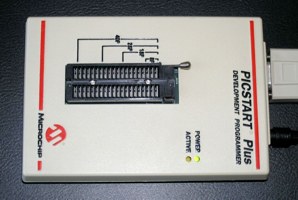
PICSTART Plus Programmer
from Microchip, incorporates the flash-upgrade kit and
latest firmware
(#DV003001,
~200.00 US-$)
|
|
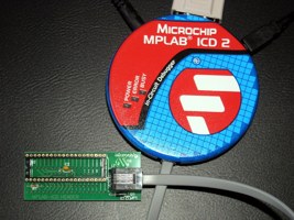
In-Circuit Debugger 2 (ICD2)
from Microchip, allowing to debug the current processor
state, internal registers and EEPROM data by setting
breakpoints in the program code within the MPLAB IDE
development environment
(#DV164005 or #DV164007,
#AC162051, ~200.00 US-$)
|
This setup programs most PIC microcontrollers (PIC12xxx,
PIC16xxx, PIC17xxx, PIC18xxx), and allows firmware updates
whenever new PIC controllers come out. I have never experienced
any issues using this commercially available programmer with the
Windows operating system (Win95, Win98, WinXP). You just have to
ensure that the intended RS232 port to use is in the range of
Com1 to Com4.
The latest version of the PICSTART Plus programmer allows
instant software-based firmware updates to the internal flash
controller. See microchipdirect.com for ordering details.
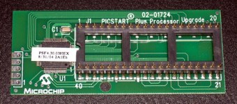
PICSTART Plus Processor Upgrade
Kit
from Microchip, includes flash-based microcontroller for
firmware upgrades
(#UK003010,
~29.00 US-$)
|
PICSTART Plus Programmer
before installing the upgrade kit, just with PIC17C44JW
and firmware v3.11
|
PICSTART Plus Programmer
after installing the PICSTART Plus Processor Upgrade
Kit
|
Years ago, I had to buy an extra PIC controller (UV-erasable
PIC17C44JW) and had to burn the corresponding firmware to it
(HEX-file supplied with MPLAB IDE). But Microchip abandoned this
re-programming procedure of the 17C44JW some times ago. Today,
the firmware upgrade of the programmer is performed directly from
MPLAB IDE, but only if you have one of the lastest flash-based
PICSTART Plus programmer, or installed the PICSTART Plus
Processor Upgrade Kit (containing a PIC18F6720) in your elderly
programmer (#UK003010, costs about 29.00 US-$, ordering information).
For ambitious starters, I recommend to order:
- In-Circuit Debugger 2 (ICD2): #DV164005 or #DV164007
(additional RS232 cable & power supply)
- 40 pin ICD header: #AC162051
- optional: Universal Programming Module for ICD2:
#AC162049
Note that with ICD2:
- the PIC16F87x can be both, in-circuit debugged and
programmed
- the PIC16F7x can only be programmed
- the PIC16F84A can only be programmed
Please see also the latest* README text files for PICSTART
Plus (17 kB) & ICD2
(32 kB)
* by 19.06.2005
|
Citing Microchip's readme.txt of PICSTART Plus
programmer:
"Program and read problem of PIC16F87X
PIC16F87X devices are shipped with low-voltage
programming enabled. PICSTART Plus programmer uses the
high-voltage programming method. Some devices do not exit
programming mode properly if low-voltage programming is
enabled, resulting in invalid read and programming
operations.
Place a 10 Kohm resistor between the RB3 pin and one
of the ground pins on the programming socket. Refer to
the device datasheet for the pinout of the specific
device."
|
First steps in PIC
programming [Toc] [Top]
As first step, read the documentation of your controller,
especially the memory and register architecture, the instruction
set (PIC Instruction Set Quick Reference) and the I/O
port section. Then try to implement a blinking LED application
using the PIC16F84 and a busy loop for waiting (you can also use
my assembler module m_wait.asm).
If your LEDs are blinking, you certainly want to connect your
controller to your PC to exchange some data. Build a RS232
hardware setup with a MAX232 level shifter and a PIC. If you use
the PIC16F84, the RS232 communication must be done by software.
You can use the 'Simple RS232 interface'. Try first to burn
the provided HEX-file onto the PIC16F84 to check for proper
hardware setup. Once everything is working well, you can get the
assembler source code and change the content according to your
needs.
Valuable Quick References
[Toc] [Top]
| MPLAB
IDE Quick Reference (DS51410B) |
Quick reference for application
development with MPLAB IDE. Summary of tools, wizards,
messages/warnings, conditional assembly, macros, samples of
absolute and relative assembler code, tips & tricks,
keyboard shortcuts.
(PDF, 188 kB) |
| MPASM/MPLINK Quick Reference (DS30400G) |
Quick reference for Microchip PIC
assembler. Summary of MPASM control directives, MPLINK
linker usage and command line options, and the individual
instruction sets of PIC10/12/16/18 devices.
(PDF, 81 kB) |
| PIC Instruction Set Quick Reference |
Quick reference of all PIC instructions,
including special instruction mnemonics. This data sheet
was extracted from document DS33014G, MPASM User's
Guide, pp. 196-209.
(PDF, 116 kB) |
Common programming questions
[Toc] [Top]
Question: What kind of instructions are BANK1 and
BNEQ?
Answer: These are my standard macro definitions
declared in the module file m_bank.asm. If
you include this module file in your main program, you can make
use of these instruction macros. For instance, the macro BANK1
performs a memory bank change to bank 1. Further, the macro BNEQ
0x23,LAB1 translates to 'branch on not equal w and 0x23'
and performs a jump to label LAB1, if the working register
w does not match the value 0x23.
Question: What kind of instructions are BNZ and SKPNZ,
since they are not listed in the Instruction Set Chapter of my
PIC controller?
Answer: These are 'Special Instruction
Mnemonics' listed in Table B.11 in the PIC
Instruction Set Quick Reference, i.e. built-in mini-macros of
the MPLAB assembler. For instance, SKPNDC translates as 'Skip
on no digit carry' and simply assembles BTFSC 3,1.
How to
assemble PIC code in MPLAB [Toc] [Top]
Only declare the main assembler file as source file in the
MPLAB project. For instance, this is the file PIC_Test.asm in the
project PIC_Test.mcp below on the picture. It will generate a
HEX-file named PIC_Test.hex when you execute 'build' or 'build
all'. Ensure that the pathes to the include files exist - or
remove the pathes and copy the include files to the directory of
the main source.
The include files must not be listed for separate compilation
under the MPLAB Project. They are just included in the main
source through include statements. During assembly time (MPASM),
these files are just inline expanded and treated as normal
assembler code. Separate compilation is neither needed nor
possible, since the code of these modules has been written for
inline compilation and (initially for simplicity) does not
contain any object or linker directives.
Of course, when project size and complexity increases, one may
consider to rewrite the code to object-based sources...
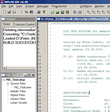
MPLAB IDE
showing the project source file (PIC_Test.asm) to be
assembled by MPASM.
|
Advanced
steps in PIC programming [Toc] [Top]
General [Toc] [Top]
Once the communication between the PIC controller and the PC
is running successfully, I suggest to implement a visual
interface on your peripheral device (the PIC controller). This
can be done easiest by using a commonly available dot matrix LCD
and one of my LCD assembler modules.
If more sophisticated I/O functionality is desired, you can
consider to attach a standard AT keyboard (ordinary PS/2 PC
keyboard) to the microcontroller. Look therefore at the AT keyboard
projects.
Paging - large code considerations
[Toc] [Top]
When your code grows, you will run into the architectural
issues of the PIC microcontroller. The PIC instruction set has
been defined - in early days - as a natural engineering trade-off
between functionality and program memory requirements. One
advantage of a larger instruction word width is the increase in
direct addressable space for immediate instructions, e.g.
'CALL Label' with Label resolved to a program
memory location by the linker/assembler. On the contrary, larger
instruction word width require more program memory, what results
in larger chip area and therefore higher manufacturing costs.
The PIC16xxx microcontroller series features immediate address
instructions (e.g. 'CALL' or 'GOTO'), which support
11 bit immediate values. Using 11 bits for immediate addressing,
we can only address 2k words in the program memory. But what if
we want to support larger memory space? One possibility to work
around this limitation is to introduce a new instruction in order
to jump between the different 2k memory blocks. That's why we
need to deal with the upper two bits ([4:3]) of the PCLATH
register. These bits cannot be altered with 'CALL' or
'GOTO' instructions, but need to be set manually before
the jump.
There is quite a good discussion and elaboration of methods to
deal with paging for the PIC16xxx microcontrollers on this site.
Using the MPLAB
IDE simulation infrastructure (MPSIM)
[Toc] [Top]
There exists a convenient built-in instruction-accurate
simulator within MPLAB IDE, called MPSIM. You can enable the
MPSIM simulator through the Debugger menu: Debugger -> Select
Tool -> MPLAB SIM.
I used it successfully for various projects, for instance
for:
- RS232 character acquisition: Using a self-created stimulus
file RS232_Stimulus_9600.sbs, it
simulates the reception of character 'u' (equal to b'01110101')
with one start bit, 8 data bits (LSB first), no parity bit, and
one stop bit.
- R/C servo signal acquisition (pulse width measurement): For
a self-made and programmable R/C servo reverse circuit using a
PIC12F615, the incoming servo signal (i.e., R/C receiver output
signal) is simulated within MPSIM using a specific stimulus
file ServoPulses_01.sbs, which performs in
total five pulses: The first two input pulses (width:
0.75 ms, 2.25 ms) are outside specifications and
check the correct error handling of the program, the next three
pulses exercise normal operating conditions (width:
0.95 ms, 2.05 ms, 1.5 ms).
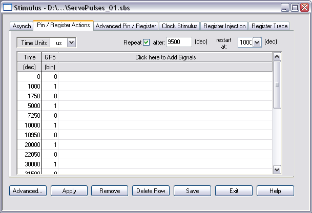
Stimulus application in MPSIM simulator
Manual stimulus creation for R/C servo signal acquisition
applying a total of five pulses: 0.75 ms,
2.25 ms, 0.95 ms, 2.05 ms, 1.5 ms.
The sequence is repeated after another 9.5 ms,
restarting at 1 ms.
|
(0) SIM-N0001 Note:
Stimulus actions after 0 us
(1000) SIM-N0001 Note: Stimulus actions after
1000 us
(1750) SIM-N0001 Note: Stimulus actions after
1750 us
(5000) SIM-N0001 Note: Stimulus actions after
5000 us
(7250) SIM-N0001 Note: Stimulus actions after
7250 us
(10000) SIM-N0001 Note: Stimulus actions
after 10000 us
(10950) SIM-N0001 Note: Stimulus actions
after 10950 us
(20000) SIM-N0001 Note: Stimulus actions
after 20000 us
(22050) SIM-N0001 Note: Stimulus actions
after 22050 us
(30000) SIM-N0001 Note: Stimulus actions
after 30000 us
(31500) SIM-N0001 Note: Stimulus actions
after 31500 us
(41000) SIM-N0001 Note: Stimulus actions
after 1000 us
(41750) SIM-N0001 Note: Stimulus actions
after 1750 us
|
MPSIM simulator output
Messages of the MPSIM simulator concerning the applied
external stimuli.
|
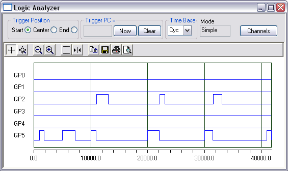
Graphical verification of stimulus application
and output generation
The applied stimuli and generated output signals can be
graphically verified by using the built-in logic analyzer
in conjunction with MPSIM. It can be quickly ensured,
that the desired stimuli are applied at pin GP5, and the
output PWM signal is generated at pin GP2 - by
ignoring the two out-of-spec input pulses at the very
beginning.
|
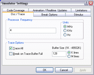
MPSIM simulator settings
Check the correct project settings for simulation:
4 MHz device clock, enable 'trace all' for logic
analyzer support within simulation, adjust the trace
buffer (128 k lines).
|
Below a screenshot of a code assessment using the MPSIM
simulator, external stimuli, and the stopwatch provided by the
MPLAB IDE. It shows the the correct value of 2.05 ms for the
R/C servo signal output - after 'reversing' an acquired input
signal of 950 us. So MPSIM has been used for quick
functional verification of code having been developed from
scratch - without any real hardware involved. In fact, I didn't
have the hardware at hand during code development.
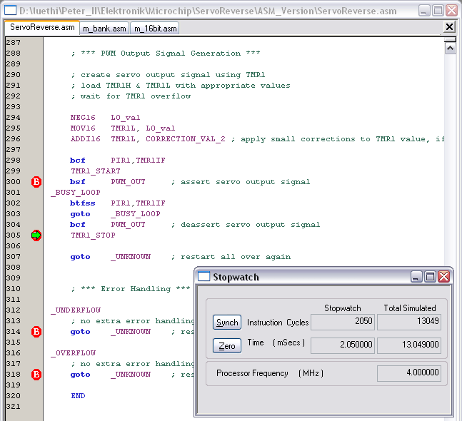
Using the Stopwatch within MPSIM for assembler
code
The stopwatch is a very convenient tool to assess the
performance of specific code sections. It can also be
used for verification of selected functionality, e.g., as
depicted, the correct R/C servo signal reversing based on
an acquired 950 us input pulse, which is finally
generating a 2050 us output pulse.
|
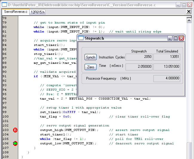
Using the Stopwatch within MPSIM for C
code
The stopwatch of MPLAB IDE can also be used to assess
code developed in high-level languages.
|
High-level
languages [Toc]
[Top]
C compiler [Toc] [Top]
There exist several commercial solutions to program the PIC
microcontroller in C. In the past, little of them were available
for free - but this has fortunately changed recently. Please see
the list of free C compilers below.
A very interesting C compiler comparison is provided by CCS,
Inc.
Please note, that this information is not independently verified,
but are rather volunteer contributions.
List of free C
compilers [Toc]
[Top]
This list can not be regarded as exhaustive - last update:
2010/05/11
If you know other free C compilers, you are kindly requested
to
email me. I will add it to the list below.
- A student edition of Microchip's C18 compiler for PIC18
MCUs is available for free on this site.
For 60 days, it is the full version of the PIC C18 compiler.
Afterwards, the optimizations related to procedural abstraction
and to the extended instruction set of the newer PIC18XXXX
devices will be disabled. Code compiled after the expiration
date will function but may occupy more memory space. (No
personal experience with this compiler.)
- A limited edition of HI-TECH's PIC C compiler for the
PIC10/12/16 MCU family is available for free on this site. The HI-TECH PICC-Lite compiler is free,
but with limitations in memory usage and device support, and
all optimization techniques are disabled. Due to program memory
constraints, support for printing floating-point and long data
types using printf functions is not included. (No personal
experience with this compiler.)
- A limited edition of SourceBoost's C compiler for
non-commercial use is available for free on this site. It supports 2 banks of RAM for
the PIC12/16/18 devices, and 2k words for the PIC12/16 and 4k
bytes for the PIC18 family. See also licensing and limitations. (No personal
experience with this compiler.)
- There exists an open source project called Small Device C
Compiler (SDCC). SDCC is a retargettable, optimizing ANSI -
C compiler that targets the Intel 8051, Maxim 80DS390, Zilog
Z80 and the Motorola 68HC08 based MCUs. Work is in progress on
supporting the Microchip PIC16 and PIC18 series. SDCC is Free
Open Source Software, distributed under GNU General Public
License (GPL). (No personal experience with this
compiler.)
Commercial C
compilers [Toc]
[Top]
Personally, I use the CCS C compiler for developing PIC
microcontroller code in a high-level language. I can recommend
this compiler, although I regard it as a professional tool with
respect to quality and pricing. The CCS C compiler can be ordered
with its own integrated development environment (IDE), but also
has a plugin for seamless integration into the Microchip MPLAB
IDE.
In general, it is quite useful to cross-check the assembler code
generated from C sources to get an impression what preconditions
have been assumed by certain C functions. For instance,
get_timerX() assumes a running timer and therefore generates more
code than necessary in case a timer being halted is considered.
Moreover, the granularity concerning the control of underlying
hardware blocks is usually coarse-grained. For instance, the
timer can not be halted and restarted with given C functions
(only disabled and reconfigured/enabled), instead, we need to
resort to our own specific declarations in order to gain access
to such functionality, as shown for timer 1 in the box
below.
The
CCS command-line C compiler for 14-bit opcode PIC devices,
e.g., PIC12F615, PIC12F683, PIC16F84, PIC16F877, PIC16F887, is
prepared for seamless integration into MPLAB IDE and starts at
150 US-$.
Notes on the C code below:
- By using the #BIT and #BYTE statements instead of plain
inline assembler code, I seek to properly address the bank/page
characteristics of these special function registers (SFRs) -
inherent to the PIC architecture and mandatory to be known by
any high-level language compiler - by delegating the correct
handling to the C compiler.
- Employing call by reference for function my_get_timer1()
prevents the introduction of any additional temporary variables
(scratch RAM for the call stack, would be even partly present
in conjunction with function inlining), but directly copies the
contents from TMR1L and TMR1H to the 16-bit variable
tmr_val.
#INLINE
void start_timer1() {
#BIT tmr1_en = GETENV("BIT:TMR1ON");
tmr1_en = 0x1; // enable timer 1
}
#INLINE
void stop_timer1() {
#BIT tmr1_en = GETENV("BIT:TMR1ON");
tmr1_en = 0x0; // disable timer 1
}
#INLINE
void my_get_timer1(unsigned int16 &tmr_val) { // short
variant for halted TMR1
#BYTE hi = GETENV("SFR:TMR1H");
#BYTE lo = GETENV("SFR:TMR1L");
tmr_val = make16(hi, lo);
}
|
Debugging
hints [Toc]
[Top]
General [Toc] [Top]
- Write only small pieces of new code, whenever possible
within a simplified test program.
- Most hobby-developers have no expensive in-circuit debugger
tool (real-time debugging in the target application using
specific software, with breakpoints and register watches). Use
therefore dot matrix LCD and/or RS232 interface for
debugging.
- Use encapsulated well-verified blocks, which you put
together as parameterizable building blocks in the target
application.
- For large projects, try to use object code and the linker
provided by Microchip MPASM IDE.
Compile messages &
sanity checks [Toc] [Top]
During the code development, overly generous compilation
messages are sometimes nasty and contra-productive.
Therefore, I turn off selected compilation messages during
development by using the statements below.
However, it makes sense to temporarily re-activate those
messages.
For instance, message 302 serves to check the correct bank access
scheme for selected configuration registers.
;***** COMPILATION
MESSAGES & WARNINGS *****
ERRORLEVEL -207 ; found label after column 1
ERRORLEVEL -302 ; register in operand not in bank
0 |
Recommendation: After development of the configuration
section, temporarily turn on message 302 and check all
compilation messages concerning correct bank access for
configuration registers.
Prevent page crossings of
tables [Toc]
[Top]
To prevent unintended
page crossings of tables, seek to add unique labels to the
beginning and end of each table and provide a corresponding
check, i.e., assertion. The assertion is executed during each
compilation and ensures the integrity of the table alignment.
WelcomeTable
addwf PCL,F ; add offset to table base pointer
DT "PIC 16F84 AT Keyboard Decoder connected" ;
create table
retlw CR ; carriage return
retlw LF ; line feed
WTableEND retlw LF ; line feed
IF (high (WelcomeTable) != high (WTableEND))
ERROR "Welcome table hits page boundary!"
ENDIF |
RS232 communication issues
[Toc] [Top]
In case you have built a PIC application including serial
communication (RS232), but it does not work properly, try to
debug it the following way:
1. Write a simple PIC assembler program for the PIC16F84 using
the module m_rs096.asm, for instance
based on the existing Simple RS232
Interface. Change or extend the main loop such that it keeps
transmitting a dedicated character every second, e.g. something
like:
LOOP SEND '@'
WAITX d'16',d'7' ; 1.045 s @ 4 MHz, extended with
specific prescaler
goto LOOP |
You may also use one of the communication test programs,
commtest1.asm
or commtest2.asm,
which transmit constantly status messages '@' and echo on every
received character.
2. Setup the HyperTerminal program (Win9x, WinXP) using the
standard settings as follows:
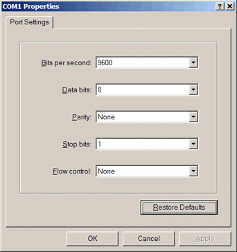
Default RS232 port settings
(9600-8-N-1)
|
Start the HyperTerminal application using the standard
settings. It should now receive a '@' every second from the PIC
microcontroller. If not, check the MAX232 and the RS232
connectors, until you receive the characters...
LCD communication issues [Toc] [Top]
Question: I can not figure out the connection between
dot matrix LCD and PIC microcontroller. Do you have a
schematic?
Answer: Basically, there is a text description in the
header section of each LCD assembler module file. But here is
also a PDF schematic to illustrate the connection between
display and controller.
Question: I have downloaded from your site the
assembler module file 'm_lcd_bf.asm' for my PIC project.
The LCD display I use is a 20x4 (CrystalFontz CFAH2004A-TMI-JP),
but it does not work. I don’t see any character and the
problem is not the contrast…
Answer: I've recently adapted some parts of the
initialization section of the LCD module files (longer wait delay
after display clear). I assume you have a newer type of display
controller than the traditional Hitachi HD44780 (PDF data
sheet, 389 kB). In case you have the LCD controller
Samsung KS0073 (PDF
data sheet, 673 kB), you have to set the constant
'LCDTYPE' to 0x1 in your main program. This adds specific
configuration commands of the new controller type, i.e. the
extended function set to set up the line count (PDF data sheet,
186 kB). You may have to adapt the line count to your
KS0073-type display in the extended function set part of
the LCD initialization section of the LCD module file (e.g.
m_lcde.asm).
If this does not help, try to use longer delays for the
initialization procedure.
Below the declarations for the module file
m_lcde.asm.First try the circuit with a 4 MHz
crystal, later on with 20 MHz. If this does not work, you
may have to adapt the initialization section to your specific
display controller (latency, commands). But first try with the
standard settings for PIC16F7x and 4 MHz:
LCDtris equ TRISD ;
LCD data on low nibble of portD
LCDport equ PORTD
#define LCD_ENtris TRISE,0x00 ; EN on portE,0
#define LCD_EN PORTE,0x00
#define LCD_RStris TRISE,0x01 ; RS on portE,1
#define LCD_RS PORTE,0x01
#define LCD_RWtris TRISE,0x02 ; RW on portE,2
#define LCD_RW PORTE,0x02
CONSTANT BASE = 0x20 ; base address of user file
registers
#include "..\m_bank.asm"
#include "..\m_wait.asm"
#include "..\m_lcde.asm" |
In case of failure, ensure that you do not use the temporary
registers at BASE+0 - BASE+3 elsewhere in your code, especially
not in your interrupt service routine (ISR)! If this setup works
perfectly, you may upgrade to the more efficient LCD modules
m_lcde_bf.asm or m_lcdexbf.asm (busy flag instead
of wait loop).
In case of errors
[Toc] [Top]
Compile errors [Toc] [Top]
If you cannot compile the projects and errors like below
appear, you did not specify the path to your include files
correctly.
Check the '#include' statements:
#include
"..\m_bank.asm"
#include "..\m_wait.asm"
#include
"..\m_rs096.asm"
|
Examples of errors generated by wrong '#include'-pathes:
Executing:
"C:\Tools\HW\Microchip\MPASM Suite\mpasmwin.exe" /q /p16F84
"LCDx_test.asm" /l"LCDx_test.lst" /e"LCDx_test.err"
Error[101] ..\..\M_LCD.ASM 113 : ERROR: (Missing include
file: m_bank.asm)
Error[101] ..\..\M_LCD.ASM 116 : ERROR: (Missing include
file: m_wait.asm)
Error[113] ..\..\M_LCD.ASM 279 : Symbol not previously
defined (LCDclk)
Error[113] ..\..\M_LCD.ASM 283 : Symbol not previously
defined (LCDclk)
Error[122] ..\..\M_LCD.ASM 290 : Illegal opcode (WAIT)
Error[122] ..\..\M_LCD.ASM 296 : Illegal opcode
(LCDWAIT)
Error[116] ..\..\M_LCD.ASM 184 : Address label duplicated
or different in second pass (BANK0)
Error[108] ..\..\M_LCD.ASM 189 : Illegal character (4)
Error[113] ..\..\M_LCD.ASM 193 : Symbol not previously
defined (LCDclk)
Error[122] ..\..\M_LCD.ASM 194 : Illegal opcode
(LCDWAIT)
Error[113] ..\..\M_LCD.ASM 200 : Symbol not previously
defined (LCDclk)
Error[122] ..\..\M_LCD.ASM 201 : Illegal opcode
(LCDWAIT)
Error[113] ..\..\M_LCD.ASM 205 : Symbol not previously
defined (LCDclk)
Error[122] ..\..\M_LCD.ASM 206 : Illegal opcode
(LCDWAIT) |
Page
crossings [Toc]
[Top]
Although most of my code is below the critical size of 2k
instruction words, page crossings may occur if you extend the
assembler source code to your needs. Please read the
recommendations about paging above.
PIC history
[Toc] [Top]
Below are some interesting text snippets found on the web
about the history of Microchip PIC controllers.
Call it RISC...
[Toc] [Top]
Citing John Bayko (Tau),
<john.bayko@sk.sympatico.ca>:
A complete version of John Bayko's interesting 'Great
Microprocessors of the Past and Present' may be retrieved at
http://jbayko.sasktelwebsite.net/cpu.html.
The roots of the PIC originated at Harvard university for a
Defense Department project, but was beaten by a simpler (and more
reliable at the time) single memory design from Princeton.
Harvard Architecture was first used in the Signetics 8x300, and
was adapted by General Instruments for use as a peripheral
interface controller (PIC) which was designed to compensate for
poor I/O in its 16 bit CP1600 CPU. The microelectronics division
was eventually spun off into Arizona Microchip Technology (around
1985), with the PIC as its main product.
The PIC has a large register set (from 25 to 192 8-bit registers,
compared to the Z-8's 144). There are up to 31 direct registers,
plus an accumulator W, though R1 to R8 also have special
functions - R2 is the PC (with implicit stack (2 to 16 level),
and R5 to R8 control I/O ports. R0 is mapped to the register R4
(FSR) points to (similar to the ISAR in the F8, it's the only way
to access R32 or above).
The PIC16x is very simple and RISC-like (but less so than the
RCA 1802 or the more recent 8-bit Atmel AVR microcontroller which
is a canonical simple load-store design - 16-bit instructions,
2-stage pipeline, thirty-two 8-bit data registers (six usable as
three 16-bit X, Y, and Z address registers), load/store
architecture (plus data/subroutine stack)). It has only 33 fixed
length 12-bit instructions, including several with a
skip-on-condition flag to skip the next instruction (for loops
and conditional branches), producing tight code important in
embedded applications. It's marginally pipelined (2 stages -
fetch and execute) - combined with single cycle execution (except
for branches - 2 cycles), performance is very good for its
processor catagory.
The PIC17x has more addressing modes (direct, indirect, and
relative - indirect mode instructions take 2 execution cycles),
more instructions (58 16-bit), more registers (232 to 454), plus
up to 64K-word program space (2K to 8K on chip). The high end
versions also have single cycle 8-bit unsigned multiply
instructions.
The PIC16x is an interesting look at an 8 bit design made with
slightly newer design techniques than other 8 bit CPUs in this
list - around 1978 by General Instruments (the 1650, a successor
to the more general 1600). It lost out to more popular CPUs and
was later sold to Microchip Technology, which still sells it for
small embedded applications. An example of this microprocessor is
a small PC board called the BASIC Stamp, consisting of 2 ICs - an
18-pin PIC16C56 CPU (with a BASIC interpreter in 512 word ROM
(yes, 512)) and 8-pin 256 byte serial EEPROM (also made by
Microchip) on an I/O port where user programs (about 80 tokenized
lines of BASIC) are stored.
Scientific curiosity [Toc] [Top]
Citing Len Umina <umina@kirk.mchip.com> from http://www.brouhaha.com/~eric/pic/faq.txt:
Actually, the PIC architecture was first integrated by
Signetics for a company in San Jose (Scientific Memory Systems as
I recall) using Bipolar technology and dubbed the 8X300. Prior to
that, the architecture had been a scientific curiosity since its
invention by Harvard University in a Defense Department funded
competition that pitted Princeton against Harvard.
Princeton won the competition because the mean time between
failure (MTBF) of the simpler single memory architecture was much
better, albeit slower, than the Harvard submission. With the
development of the transistor and IC's, the Harvard Architecture
is finally coming into its own.
Microchip has made a number of enhancements to the original
architecture, and updated the functional blocks of the original
design with modern advancements that are in concert with existing
architectural processes and enabled by the low cost of
semiconductors.
From I/O
handling to RISC controller [Toc] [Top]
Citing Alex R. Baker <alex@microchp.demon.co.uk> from
http://www.brouhaha.com/~eric/pic/faq.txt:
Back in 1965, General Instruments (GI) formed a
Microelectronics Division, and indeed used this division to
generate some of the earliest viable EPROM and EEPROM memory
architectures. As you may be aware, the GI Microelectronics
Division were also responsible for a wide variety of digital and
analog functions, in the AY3-xxxx and AY5-xxxx families.
GI also generated a 16 bit microprocessor, called the CP1600,
in the early 70s. This was a reasonable microprocessor, but not
particularly good at handling I/Os. For some very specific
applications where good I/O handling was needed, GI designed a
Peripheral Interface Controller (or PIC for short), in around
1975. It was designed to be very fast, since it was I/O handling
for a 16 bit machine, but didn't need a huge amount of
functionality, so its microcoded instruction set was small.
Hopefully, you can see what's coming....yes, the architecture
designed in '75 is substantially the PIC16C5x architecture today.
Granted, the1975 version was manufactured in NMOS, and was only
available in masked ROM versions, but still a good little uC. The
market, however, didn't particularly think so, and the PIC
remained designed in at a handful of large customers only.
During the early 80s, GI took a long hard look at their
business, and restructured, leaving them to concentrate on their
core activities, which is essentially power semiconductors.
Indeed they are still doing this very successfully now. GI
Microelectronics Division became GI Microelectronics Inc. (a
wholly owned subsidiary), which in 85% was finally sold to
venture capital investors, including the fab in Chandler,
Arizona. The venture capital people took a long hard look at the
products in the business, and got rid of most of it - all the
AY3- and AY5- parts and a whole bunch of other stuff, leaving the
core business of the PIC and the serial and parallel EEPROMs. A
decision was taken to restart the new company, named Arizona
Microchip Technology, with embedded control as its differentiator
from the rest of the pack.
As part of this strategy, the PIC165x NMOS family was
redesigned to use one of the other things that the fledgling
company was good at, i.e. EPROM - the concept of the CMOS based,
one-time-programmable (OTP) and eraseable EPROM program memory
PIC16C5x family was born.
Last updated: 2010/05/19
[Toc] [Top]